
A Battery Management System is an electronic control unit integrated into every modern EV battery pack. It performs three essential roles: it monitors battery conditions in real time, it protects cells from dangerous operating states, and it optimizes performance to extend battery life.
Every lithium-ion battery cell in an EV has a safe operating window — typically 2.5V to 4.2V per cell and 0°C to 60°C operating temperature. Outside these ranges, cells degrade rapidly or enter thermal runaway, a self-accelerating overheating reaction that can destroy the pack. The BMS prevents this by continuously measuring voltage, current, and temperature at individual cell level — often sampling thousands of times per second — and intervening the instant any parameter approaches its limit.
For charging station operators, this matters because the BMS is the component that authorizes every single charging session. Without a functioning BMS sending the correct digital signals, even a 720 kW liquid-cooled supercharger cannot deliver a single watt.
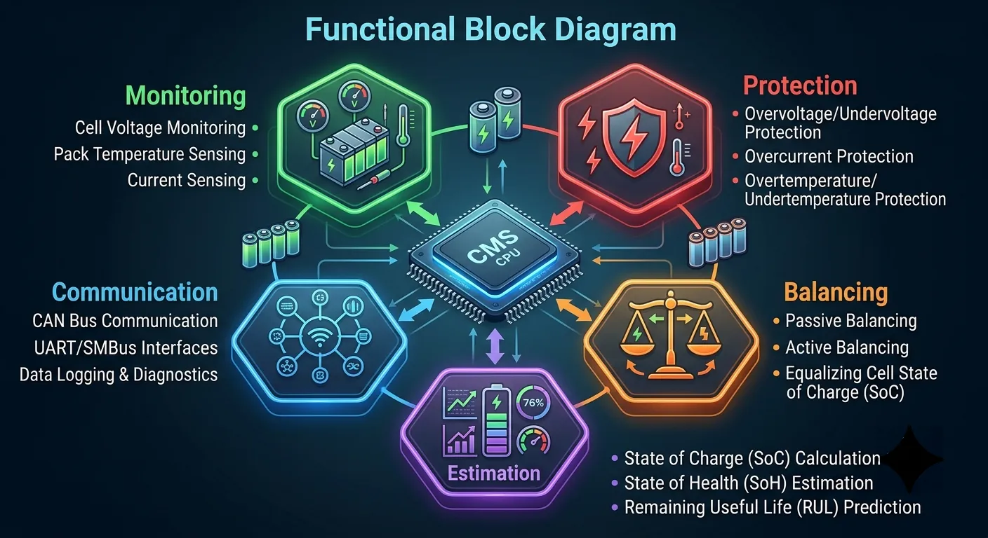
Core BMS Functions
| Function | What It Does | Relevance to Charging |
|---|---|---|
| Cell Monitoring | Measures voltage, current, temperature per cell | Determines max charge rate the battery can safely accept |
| State Estimation | Calculates SOC and SOH | Tells the charger when to slow down (typically above 80% SOC) |
| Cell Balancing | Equalizes voltage across all cells in the pack | Prevents premature charge termination from voltage imbalance |
| Thermal Management | Controls cooling/heating to maintain 15–35°C range | Prevents thermal derating during high-power DC fast charging |
| Safety Protection | Opens contactors if overvoltage/overtemp/overcurrent detected | Can instantly terminate any charging session to prevent damage |
How the BMS Communicates with an EV Charger
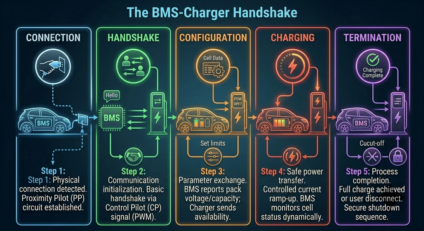
Before any current flows, the BMS and the charger perform a digital handshake — a multi-stage negotiation that verifies compatibility, exchanges charging parameters, and establishes the maximum safe charging rate. This process typically completes in 1–3 seconds but can take longer if firmware versions are mismatched or connector pins are worn.
The BMS-Charger Handshake: Step by Step
- Physical Connection Detection: The charger detects the connector insertion and checks the proximity pilot (PP) and control pilot (CP) signals.
- Insulation Monitoring: The charger performs an insulation resistance test between high-voltage lines and chassis ground — typically completed within 500 ms.
- BMS Wake-Up: The charger sends a wake-up signal through the CP line; the BMS responds by powering on and running a self-diagnostic.
- Parameter Negotiation: The BMS sends its charging parameters via CAN bus (on CCS and GB/T) or PLC (on CHAdeMO): maximum voltage, maximum current, target SOC, and cell temperature limits.
- Pre-Charge Circuit Activation: The charger’s output voltage ramps up to match the battery’s current open-circuit voltage to prevent inrush current.
- Main Contactor Closure: Once voltages match, the BMS closes the main battery contactors and current begins flowing.
- Continuous Monitoring: Throughout the session, BMS updates are transmitted every 100 ms. If any parameter exceeds its limit, the BMS signals the charger to reduce or stop output immediately.
Operator insight: When drivers report that a charger “won’t start,” the root cause is typically a BMS handshake failure at step 2, 3, or 4. The most common culprits are firmware version mismatches between the charger and a specific EV model, worn connector pins that degrade the pilot signal, or outdated charger-side protocol implementations.
BMS Communication Protocols by Connector Standard
| Connector Standard | BMS Protocol | Physical Layer | Primary Markets |
|---|---|---|---|
| CCS | CAN bus (ISO 11898) | Two-wire differential | Europe, North America |
| CHAdeMO | CAN bus + analog | Dedicated signal lines | Japan, legacy global |
| GB/T DC | CAN bus (GB/T 27930) | Two-wire differential | China |
| NACS (J3400) | PLC (ISO 15118) | Power line carrier | North America |
BMS and DC Fast Charging: Why Speed Depends on the Battery Brain
The BMS determines the maximum DC input rate — the highest charging power the battery can physically accept. This is not fixed; it varies continuously based on SOC, cell temperature, and battery age. A vehicle rated at 250 kW input will only achieve that rate when conditions are optimal. As the battery fills, the BMS progressively reduces the accepted charge rate to protect cells from lithium plating and excessive heat generation.
This is why DC fast charging slows dramatically above 80% SOC — the BMS is deliberately throttling input power to protect the battery, not because the charger is underperforming. Operators who understand this can plan session turnover windows around the 0–80% range.
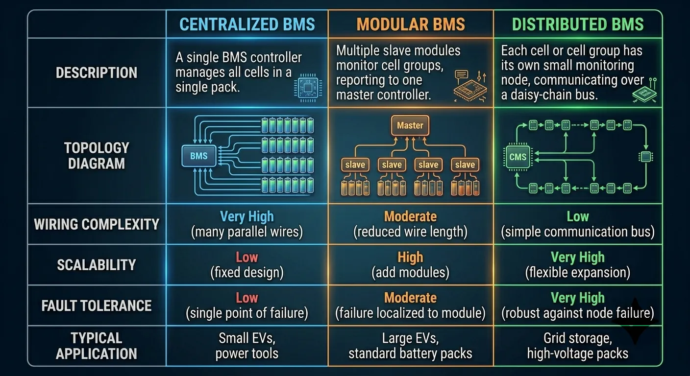
BMS Architecture Types: Centralized vs Distributed vs Modular
| Architecture | Design | Typical Application | Cost |
|---|---|---|---|
| Centralized | Single BMS controller with wired connections to all cells | Small packs (<20 kWh), e-bikes, PHEVs | Low |
| Distributed | Slave modules per cell group with local processors, communicate to master BMS | Most production EVs (Tesla, VW MEB, Hyundai E-GMP) | Medium |
| Modular | Multiple independent BMS units, each managing a sub-pack; master BMS coordinates | Commercial vehicles, buses, large trucks | Medium-High |
BMS Technology Trends in 2026
The global BMS market is projected to reach $30.1 billion by 2030, growing at 26.6% CAGR. Several technology shifts are reshaping BMS design in ways that directly affect charging infrastructure:
- AI-Driven State Estimation: Over 40% of new BMS designs now incorporate machine learning algorithms for SOC and SOH estimation, replacing traditional Kalman filtering with neural networks trained on fleet-wide battery aging data.
- Wireless BMS (wBMS): Replacing wired cell monitoring with wireless communication reduces wiring harness weight by up to 90%. General Motors adopted wBMS across its Ultium platform. For infrastructure operators, wireless BMS has no impact on charger compatibility because the BMS-to-charger interface remains wired.
- ISO 15118 and Plug & Charge: Enables automatic vehicle authentication, billing, and charging parameter exchange as soon as the connector is inserted — eliminating the need for apps, RFID cards, or payment terminals.
- Solid-State Battery Readiness: Solid-state batteries require BMS designs handling wider voltage windows, higher energy density, and fundamentally different thermal behavior.
How Charging Equipment Supports Reliable BMS Communication
For charging station operators, the BMS is not directly controllable — it lives inside the vehicle. But the charger can be selected, configured, and maintained to communicate reliably with the full diversity of BMS implementations across the vehicle fleet:
- Multi-Protocol Support: A commercial charger should support CAN bus communication across CCS1, CCS2, GB/T, and CHAdeMO protocols. Single-protocol chargers create silent incompatibilities.
- OCPP Integration: When the charger supports OCPP, BMS session data is relayed to the CMS for remote diagnostics, predictive maintenance, and load management.
- Firmware Update Capability: Chargers with OTA firmware update capability stay compatible with evolving vehicle fleets without requiring on-site technician visits.
- Diagnostic Logging: Chargers that log BMS handshake data provide operators with forensic evidence to diagnose session failures and identify patterns across vehicle models.
The BMS is the most important electronic component in an EV that charging station operators never directly control. Understanding how it works — how it communicates, what it protects, and why it sometimes refuses a session — transforms the operator’s ability to diagnose problems, select compatible equipment, and deliver a reliable charging experience.
Klitv delivers reliable EV charging solutions through Zhengzhou Klitv Equipment Co., Ltd., established in 2020 with full independent export qualifications. Our chargers feature robust 2.0mm thickened steel body construction, high-precision parts, and intelligent software that supports comprehensive BMS communication across CCS, GB/T, and CHAdeMO protocols. With over 800 professional engineers, we help charging operators deploy infrastructure that works reliably with the full diversity of vehicles their customers drive.
Ready to build a more reliable charging network? Contact our team today to discuss your project requirements, or browse our full product range to find the right chargers for your application.