
The control pilot EV charging signal is a low-voltage PWM communication mechanism defined by IEC 61851-1. It governs the handshake between an EV charger and a vehicle by detecting the connection, confirming the vehicle is ready, and telling it the maximum available charging current. Without the CP signal, no AC charging session can begin.
Consider what happened at a logistics depot in Bangkok last year. The facility had installed 20 brand-new DC chargers for its electric delivery fleet. Within the first month, three units began failing intermittently, trucks would plug in, the charger would click, and then nothing. Technicians initially suspected defective power modules, ordering costly replacements that took weeks to ship from the factory. When an electrical engineer finally visited the site, the diagnosis took 15 minutes: one cable had a fractured control pilot wire from repeated tight coiling around the charger body, and two other connectors had corroded CP pins from monsoon-season moisture ingress. Total repair cost: two replacement cables and a contact cleaner. The “power problem” was a communication problem all along.
This is the reality of EV charging infrastructure. The most expensive component in the cabinet is rarely the culprit. The CP signal, a humble 1 kHz square wave carried on a single pin, is the most common failure point in AC and DC charging sessions. For operators, fleet managers, and technicians, understanding this signal is the difference between a 15-minute fix and a multi-week equipment return.
This guide explains what the Control Pilot signal is, how it works through all six charging states, how to diagnose the most frequent CP faults, and why the quality of a charger’s CP circuit design directly impacts uptime and vehicle compatibility in real-world deployments.
Key Takeaways
- The Control Pilot (CP) signal is a ±12V, 1 kHz PWM square wave that manages the entire EV charging handshake, defined by IEC 61851-1 and SAE J1772
- Six voltage states (A through F) govern every phase, from idle to fault, with specific resistance values that the vehicle uses to signal its status
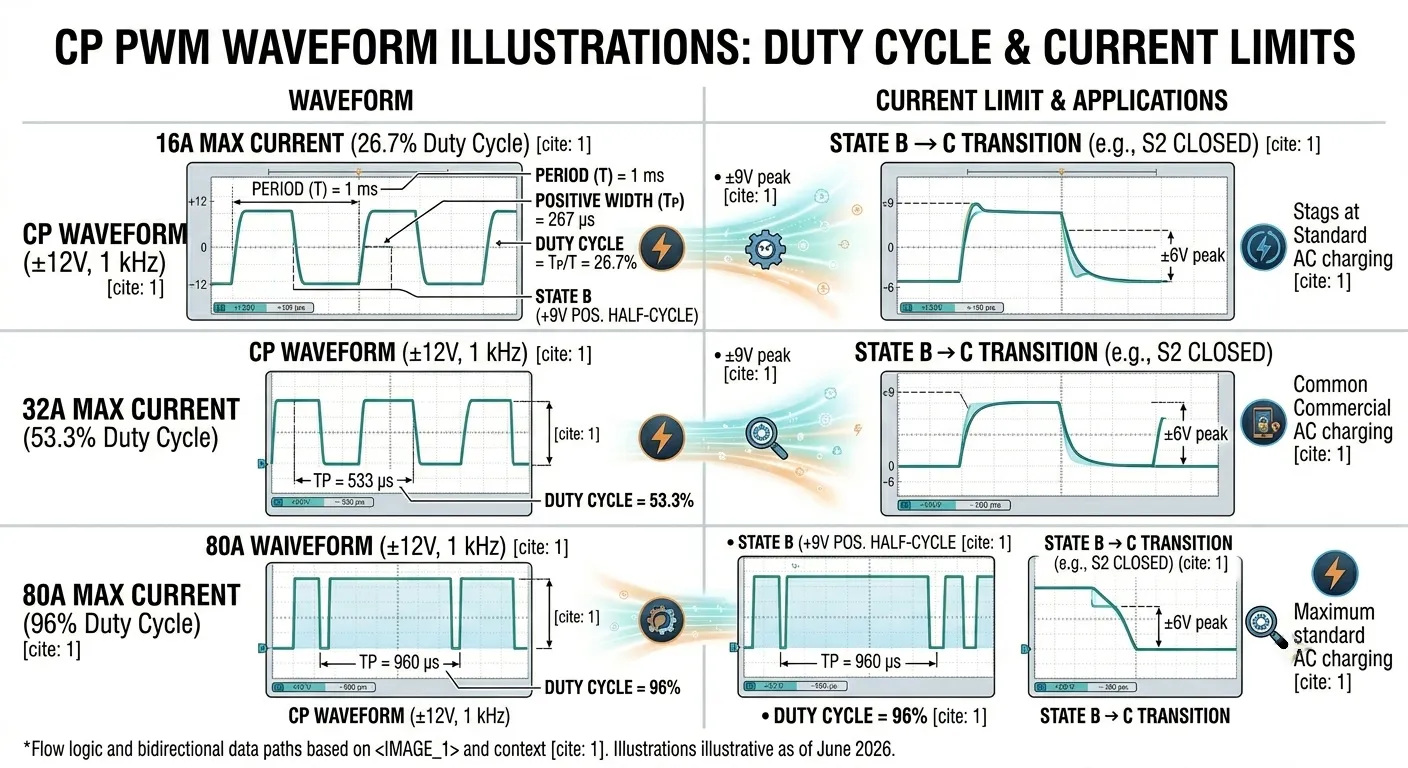
- The PWM duty cycle directly sets the maximum charging current: 26.7% duty means 16A, 53.3% means 32A, and 96% means 80A
- Industry data suggests 15–25% of failed charging sessions involve CP or Proximity Pilot (PP) faults, not power electronics failures
- A charger with a precision-engineered CP circuit, built with tight-tolerance components and factory-verified waveforms, dramatically reduces field failures versus units with loosely specified signal paths
What Is the Control Pilot (CP) Signal?
The Role of CP in the EV Charging Connector
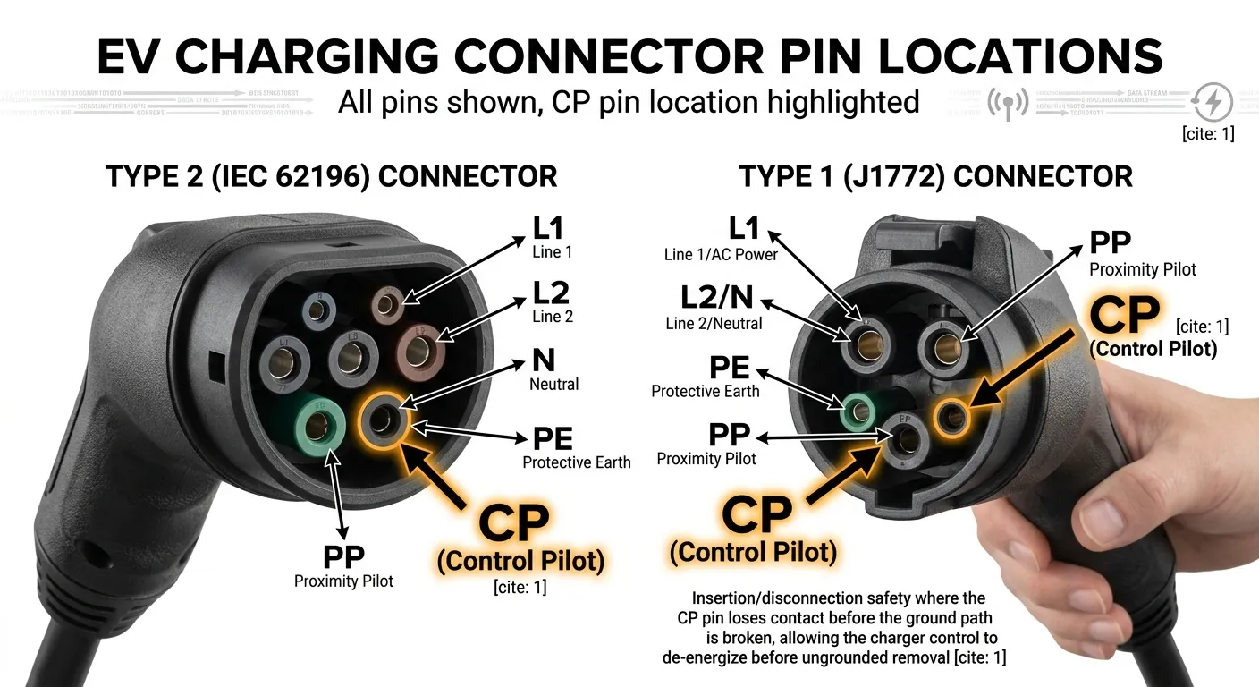
The Control Pilot pin is one of the small-diameter signal contacts in every Type 1 (SAE J1772) and Type 2 (IEC 62196) charging connector. It sits alongside the main power conductors (L1, L2/N), the Protective Earth (PE), and the Proximity Pilot (PP). While the power pins carry up to 80A of current and the PE provides the safety ground path, the CP pin’s job is entirely different: it carries information.
Physically, the CP pin is intentionally shorter than the other pins in the connector. This is a deliberate safety design. During insertion, the PE pin connects first, grounding the vehicle before anything else. The CP and power pins follow. During disconnection, the CP pin loses contact before the PE pin does, which gives the charger’s control circuitry time to de-energize the power contacts before the ground path is broken. IEC 62196-2 mandates this sequencing, and it is one of several ways the CP signal protects people and equipment.
From the perspective of a commercial EV charging operator, every charging session depends on this single pin maintaining a clean, uninterrupted connection. A bent or corroded CP pin means a charger that cannot start sessions, regardless of how well the power electronics are functioning.
CP vs. Proximity Pilot (PP), What’s the Difference?
Both the Control Pilot and Proximity Pilot appear on the same connector, and their names sound similar, but they serve fundamentally different purposes.
| Feature | Control Pilot (CP) | Proximity Pilot (PP) |
|---|---|---|
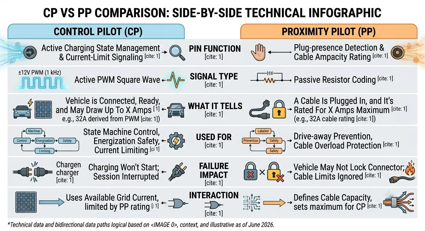
| Primary role | Active charging state management & current-limit signaling | Plug-presence detection & cable ampacity rating |
| Signal type | Active PWM square wave (1 kHz, ±12V) | Passive resistor coding (no active signal) |
| What it tells | ”The vehicle is connected, ready, and may draw up to 32A" | "A cable is plugged in, and it’s rated for 32A maximum” |
| Used for | State machine control, energization safety, current limiting | Drive-away prevention, cable overload protection |
| Failure impact | Charging won’t start; session interrupted | Vehicle may not lock connector; cable limits ignored |
Think of CP as the active conversation channel between charger and vehicle, it asks questions, receives answers, and makes decisions. Think of PP as a static ID tag, it passively reports two facts: “something is plugged in” and “this cable can handle X amps.”
The two signals do interact. The EVSE uses PP to verify the cable’s current rating, then uses CP to tell the vehicle the available current from the grid side, which may be lower than the cable’s maximum. If the PP resistor indicates a 32A cable but the circuit breaker and CP PWM are set for 16A, the on-board charger must obey the lower limit communicated via CP.
The Standards Behind CP, IEC 61851-1 and SAE J1772
The Control Pilot signal is defined primarily by two international standards:
- IEC 61851-1, The core international standard for electric vehicle conductive charging systems. It defines the six CP states (A through F), voltage levels, PWM parameters, and safety timing requirements. This standard applies across Europe, Asia, and most global markets.
- SAE J1772, The North American equivalent, defining the Type 1 connector and specifying the same CP signal characteristics as IEC 61851-1, with some regional variations for voltage tolerances and connector mechanical specifications.
- GB/T 18487.1, China’s national standard, which adopts the same CP signaling principles with adaptations for the GB/T connector form factor.
For charging station operators deploying across multiple regions, one important reality is that the CP signal fundamentals are globally harmonized. A charger designed to IEC 61851-1 will communicate correctly with any standards-compliant EV, regardless of market. Klitv chargers are engineered to comply with IEC 61851, SAE J1772, and GB/T standards, ensuring consistent CP signal performance wherever a project is located.
How the Control Pilot Signal Works, States A Through F
The 1 kHz PWM Square Wave
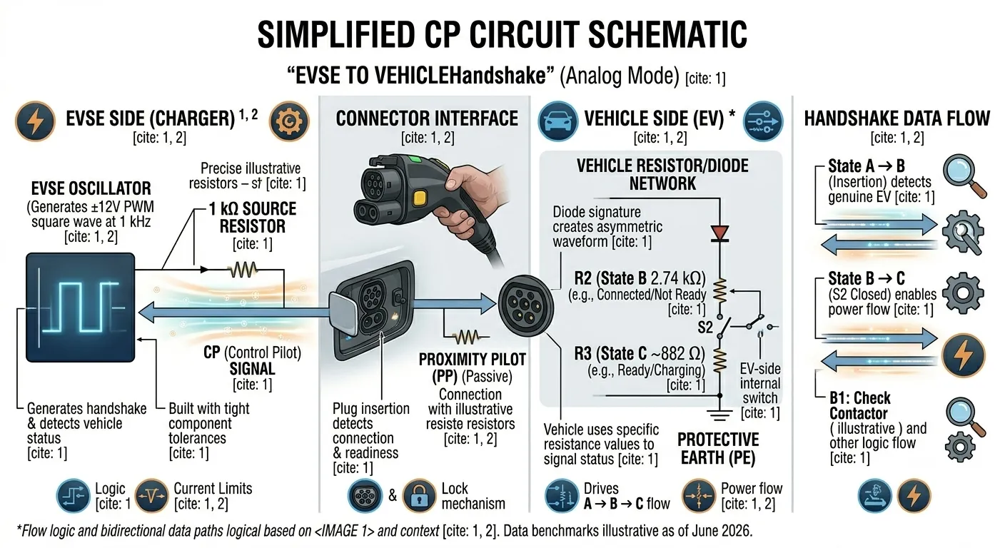
The EVSE generates a ±12V square wave at 1 kHz (980–1020 Hz, per the standard) and places it on the CP pin through a 1 kΩ source resistor. The vehicle side has resistors and a diode that load the signal, pulling the positive half-cycle voltage down to specific levels. The combination of this EVSE waveform and the vehicle’s resistive loading produces the six distinct charging states.
The diode inside the vehicle’s CP circuit is critical. By only conducting during the positive half-cycle, it creates an asymmetric waveform that the EVSE can distinguish from a simple resistive load. This prevents non-EV devices, or a short circuit from water or debris, from being misinterpreted as a connected vehicle. If the EVSE does not detect this diode signature, it will not energize the power pins, regardless of what voltage it measures.
Complete State Table, A, B, C, D, E, F
Each state corresponds to a specific phase of the charging session. The voltage levels listed below are measured at the EVSE output (CP relative to PE).
| State | Voltage (CP–PE) | Resistance (CP–PE) | Meaning |
|---|---|---|---|
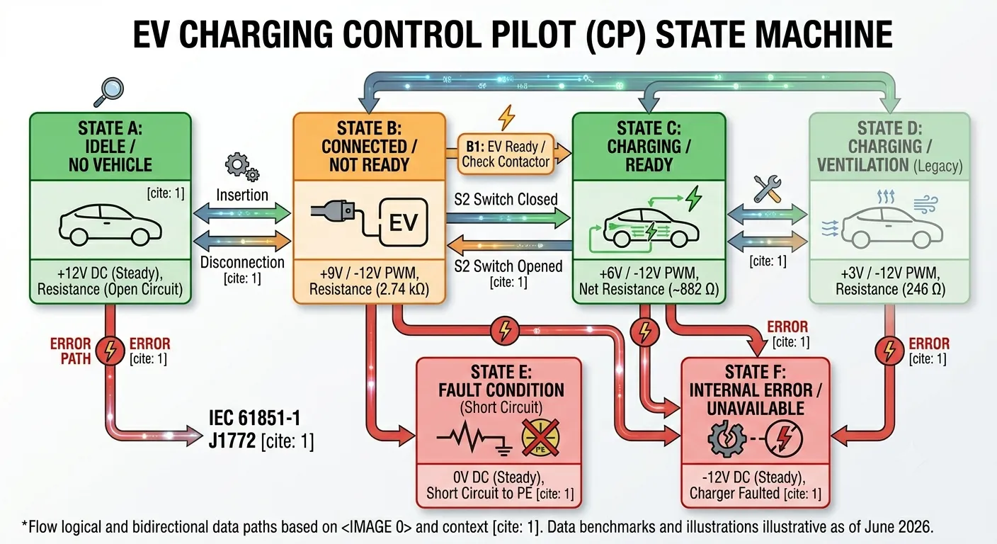
| A | +12V DC (steady) | Open circuit (∞) | No vehicle connected, charger idle |
| B | +9V / -12V PWM | 2.74 kΩ | Vehicle connected, not yet ready to accept power |
| C | +6V / -12V PWM | 882 Ω | Vehicle ready, charging in progress (no ventilation needed) |
| D | +3V / -12V PWM | 246 Ω | Vehicle ready, charging with ventilation required (legacy) |
| E | 0V | Short circuit to PE | Fault condition, power immediately cut |
| F | -12V DC (steady) | , | EVSE internal error or unavailable |
State D is rarely encountered with modern EVs, as active battery thermal management has largely eliminated the need for external ventilation signaling. It remains in the standard primarily for backward compatibility with early-generation electric vehicles.
The Charging Sequence, Step by Step
When a driver plugs in, the following sequence unfolds in under 3 seconds:
Step 1: State A → State B. The vehicle’s 2.74 kΩ resistor and diode are connected between CP and PE. The EVSE sees the positive half-cycle voltage drop from +12V to approximately +9V and detects the diode signature. The charger now knows a genuine EV is connected and begins outputting the PWM signal to communicate available current.
Step 2: State B → State C. The vehicle closes its S2 switch, placing a 1.3 kΩ resistor in parallel with the 2.74 kΩ resistor (net: ~882 Ω). The positive half-cycle drops to about +6V. This signals that the vehicle is ready to accept power. The EVSE verifies the diode is still present, then closes its internal contactors, and power flows to the vehicle.
Step 3: State C, Charging in progress. The EVSE continuously monitors the CP signal. If the vehicle needs to pause charging (battery full, scheduled stop, user interrupt), it opens S2 and the voltage returns to +9V (State B). The EVSE opens its contactors. The PWM signal continues to communicate the available current throughout the session, and smart chargers can adjust the duty cycle dynamically for load management.
Step 4: State C → State B → State A. When the session ends or the user unplugs, the sequence reverses. The critical safety requirement from IEC 61851-1: if the state changes from C to B while power is flowing, the EVSE must open its contactors within 100 milliseconds. This ensures the connector pins are de-energized before the user can physically withdraw the plug.
How PWM Duty Cycle Sets the Charging Current
The PWM duty cycle is the core EV charger communication protocol mechanism at the physical layer. The EVSE uses it to tell the vehicle: “This is the maximum current you may draw.” The vehicle’s on-board charger is obligated to respect this limit.
For duty cycles between 10% and 85%, the formula is straightforward:
Maximum Current (A) = Duty Cycle (%) × 0.6
For duty cycles between 85% and 96%, a different formula applies:
Maximum Current (A) = (Duty Cycle (%) - 64) × 2.5
Practical examples:
| Desired Current | Required Duty Cycle | Typical Application |
|---|---|---|
| 6A | 10% | Minimum charging, trickle mode |
| 16A | 26.7% | Standard home / workplace AC charging |
| 32A | 53.3% | Common commercial AC charger setting |
| 48A | 80% | High-power home / small commercial |
| 80A | 96% | Maximum standard AC charging |
A duty cycle of 5% has a special meaning, it signals that the EVSE supports high-level digital communication (ISO 15118) and that the vehicle should initiate a PLC link before charging begins.
This duty-cycle mechanism is what enables dynamic load balancing. A smart charger monitoring total building load can reduce its PWM duty cycle in real time, from 53% to 27%, for example, and the vehicle’s on-board charger will automatically reduce its current draw from 32A to 16A. No restart, no interruption, no manual intervention required.
Common Control Pilot Faults and Troubleshooting
Why Does My Charger Show a “Pilot Problem” Error?
If you operate or maintain EV chargers, you have almost certainly encountered a “Pilot Problem,” “CP Fault,” or “Control Pilot Error” on a charger display or management dashboard. Different manufacturers use different names, Wallbox displays error code 104 or 106, myenergi zappi shows “Pilot Problem,” Weidmüller reports “Invalid CP value,” and Kia portable chargers flash E1, but they all mean the same thing: the charger cannot establish or maintain a valid CP signal with the vehicle.
Here is what Maria, a facility manager at a commercial parking structure in Barcelona, discovered when two of her eight chargers started logging pilot errors every morning. The problem never appeared in the afternoon. The cause? The CP pins on the morning-shift connectors had accumulated overnight condensation in the underground garage. A quick wipe with contact cleaner each morning solved the issue entirely, no parts replaced, no service call needed. The chargers themselves were functioning perfectly; they were correctly refusing to energize when the CP signal was degraded.
Top 5 CP Fault Causes and How to Diagnose Them
1. Damaged or Fractured CP Wire in the Charging Cable
The most common CP fault, especially on tethered chargers where the cable is repeatedly coiled, uncoiled, and exposed to vehicle traffic. The thin CP conductor can fracture inside an otherwise intact cable jacket.
Diagnosis: With the charger in Fast or Always On mode, plug into a known-working vehicle. Gently wiggle the cable along its length, especially near the charger body and connector housing. If the charger clicks or errors when you flex a specific section, the CP wire is fractured at that point.
Fix: Replace the entire cable assembly. CP wires cannot be reliably spliced in the field while maintaining signal integrity.
2. Corroded or Dirty CP Pin
The CP pin is the shortest pin on the connector, recessed deeper than the power pins and PE pin. This makes it harder to clean and more susceptible to debris accumulation.
Diagnosis: Visual inspection under good light. Look for green or white corrosion deposits, black carbon tracking, or visible contamination. Try a known-good cable on the same charger, if that works, the original cable’s CP pin is the culprit.
Fix: Clean with electrical contact cleaner (zero-residue type) and a cotton swab or soft brush. For severe corrosion, replace the connector or cable. Prevent recurrence with connector holsters or weather caps when not in use.
3. Poor Grounding (PE Fault)
The CP signal is measured between CP and PE. If the PE connection has high impedance or is open, the voltage measurements become unreliable and the EVSE may enter State E (fault) or fail to detect State B.
Diagnosis: Measure PE-to-earth resistance at the charger, it should be below 0.5Ω. Check all ground connections in the distribution panel. Many chargers will refuse to start if PE continuity is not verified.
Fix: Repair the ground connection. This is a job for a qualified electrician, never bypass a PE fault.
4. Vehicle-Side Charge Port Fault
Sometimes the charger, cable, and installation are fine, the fault is in the vehicle’s charge port, on-board charger, or CP detection circuit.
Diagnosis: Test the vehicle on a different, known-working charger. If the same error occurs, the vehicle is the likely source. On vehicles that support OBD-II diagnostics, check for CP-related diagnostic trouble codes: P0CF4 (CP Circuit Performance), P0CF5 (CP Circuit Low Voltage), P0CF6 (CP Circuit High Voltage), or P0CF9 (CP Charging Switch Performance). These codes often point to faults in the Battery Management System (BMS) or charge port control module.
Fix: Refer to the vehicle manufacturer’s service procedures. Charge port replacements and on-board charger repairs are vehicle-side operations.
5. EVSE Internal CP Circuit Failure
The oscillator circuit, level-shifting amplifier, or ADC sampling circuit inside the charger can fail, especially in chargers built with loosely specified components or exposed to voltage surges.
Diagnosis: Measure the CP-to-PE voltage at the charger output with no vehicle connected. You should see +12V DC ±5% (11.4–12.6V). If you see 0V, -12V steady, or a waveform with visible distortion, the charger’s internal CP circuit may have failed.
Fix: Contact the manufacturer for repair or replacement. This is where charger build quality matters: a well-designed CP circuit with surge protection and precision components is far less likely to fail in the field.
How to Test the CP Signal, Tools and Methods
For operators and technicians who want to diagnose CP issues systematically, three levels of testing are available:
Basic (Multimeter): A digital multimeter with Min/Max capture can measure the DC voltage on the CP pin relative to PE. With no vehicle connected, expect a steady +12V DC. With a vehicle connected in State B, expect approximately +9V on the positive half-cycle. This level of testing can confirm whether a charger is generating a CP signal at all, but cannot verify PWM frequency, duty cycle, or waveform quality.
Intermediate (EV Simulator + Multimeter): Tools like the Fluke FEV100 or Beha-Amprobe EV-520 simulate an electric vehicle, presenting the correct resistances for States B, C, and D, so you can test the charger’s response across all states without a real vehicle. Combined with a true-RMS multimeter, this setup verifies state transitions, voltage levels, and basic PWM presence.
Advanced (Oscilloscope): A handheld oscilloscope connected to the CP and PE terminals lets you verify the full waveform: frequency (must be 980–1020 Hz), duty cycle accuracy, rise time (< 2 µs for State B), fall time (< 2 µs for State B), and the presence of the diode signature asymmetry. This is the definitive test for confirming CP signal integrity.
For charging network operators using a CMS to monitor their stations, remote CP diagnostics, voltage readings and state logs reported via OCPP, can often identify CP faults before a site visit is necessary, saving on service costs and reducing downtime.
CP Calibration, When and Why It Matters
Some chargers support CP line calibration, a procedure that compensates for cable length, connector contact resistance, and component tolerances in the signal path. Without calibration, these accumulated resistances can shift the measured CP voltage enough that the charger misidentifies states, showing State A when a vehicle is connected, or cycling between State B and State C during charging.
Calibration is worthwhile when you see: a vehicle is physically connected but the charger reports “no vehicle detected”; the charger frequently cycles between “charging” and “not charging” without obvious cause; or a specific vehicle model consistently fails to start on one charger but works on others.
Most calibration routines involve connecting a known-good vehicle (or EV simulator), triggering the calibration sequence via the charger’s configuration interface, and allowing the charger to measure and store offset values. The process typically takes under a minute and requires no special tools beyond what is already on site.
Beyond Basic CP, Digital Communication and Build Quality
The 5% Duty Cycle Trigger, Entering ISO 15118
The Control Pilot signal’s role extends beyond the analog state machine described so far. When the EVSE outputs a 5% PWM duty cycle, it signals that high-level digital communication is available. The vehicle’s communication controller then initiates a Power Line Communication (PLC) link using HomePlug Green PHY — a broadband signal superimposed on the same CP wire, operating at 2–30 MHz. This is the same CP-based handshake used by CCS (Combined Charging System) DC fast chargers before high-power DC delivery begins.
This digital layer, governed by ISO 15118, enables capabilities that the basic PWM signal cannot support: Plug & Charge (automatic vehicle authentication and billing without RFID cards or apps), smart charging with grid-integrated scheduling, bidirectional power transfer (Vehicle-to-Grid, per ISO 15118-20), and TLS-encrypted data exchange.
This transition is not optional for long. The EU Alternative Fuels Infrastructure Regulation (AFIR), amended in 2025, mandates that all new and refurbished public chargers comply with ISO 15118-2 from January 2026, and ISO 15118-20 from January 2027. Even the most basic CP analog handshake must now be capable of triggering a digital session.
For charging operators, this means the CP circuit in any new charger must be designed not just for clean ±12V PWM generation, but for low-noise operation that does not interfere with the PLC carrier. A poorly filtered CP oscillator can degrade ISO 15118 communication reliability, another reason why signal-path design matters for long-term deployment.
What Makes a High-Quality CP Circuit, A Manufacturer’s Perspective
When a charger fails to start a session, the operator sees downtime. When that downtime repeats across multiple units, the operator sees a reliability problem. Often, the root cause is a CP circuit designed to meet minimum specifications only. It was not built to maintain signal integrity after 18 months of thermal cycling, humidity, and grid transients.
Here is what differentiates a CP circuit built for long-term field reliability:
Tight component tolerances. The IEC 61851-1 standard requires PWM frequency accuracy of ±2% and voltage level accuracy of ±5%. A quality CP circuit uses resistors with 1% tolerance and capacitors with temperature-stable dielectrics (C0G/NP0 rather than X7R) to stay within these limits across the charger’s full operating temperature range.
Clean waveform generation. Rise and fall times must stay under 2 µs to ensure reliable state detection. Slower edges, caused by excessive capacitance in the signal path or poorly designed level-shifting amplifiers, can cause the EVSE or vehicle to misread the duty cycle, resulting in incorrect current limiting.
No recycled or unspecified components. In the CP signal path, component substitutions have direct consequences. A generic diode with higher forward voltage than specified changes the waveform shape the vehicle sees. A relay driver transistor sourced from recycled e-waste may fail after months of thermal stress. Klitv chargers use only high-precision new components, no recycled materials, across all signal and power paths.
Factory verification of every unit. Some manufacturers perform CP testing on a statistical sample basis. Klitv tests every charger’s CP circuit before packaging: verifying all six states, confirming PWM frequency and duty cycle accuracy, and validating rise/fall times against the IEC 61851-1 specification. For chargers shipping to international projects in industrial-grade wooden crate packaging, this per-unit verification means the CP circuit arrives at the installation site performing exactly as it did at the factory.
The CP signal is not glamorous. It does not appear on spec sheets alongside kilowatt ratings and charging speeds. But when an operator is managing 50 chargers across multiple locations, the difference between a well-engineered CP circuit and a barely-compliant one shows up in the uptime numbers, and in the service call log.
Conclusion
The control pilot EV charging signal is the foundation of safe, reliable EV charging. Every session, whether a 7kW overnight top-up at an apartment building or a 180kW rapid charge at a highway service station, begins with the same ±12V, 1 kHz handshake defined by IEC 61851-1. Understanding the six CP states, the PWM current-limit mechanism, and the most common failure modes is not just technical knowledge; it is operational knowledge that reduces downtime and service costs.
For charging station operators and project developers, the practical takeaway is straightforward: the CP signal is where most charging failures begin. When specifying equipment, the quality of the CP circuit design matters as much as the power rating. Clean waveforms, precision components, per-unit factory verification, and global standards compliance are not abstractions, they are the difference between a charger that works reliably for years and one that generates a steady stream of “pilot problem” tickets.
Klitv chargers are designed with this reality in mind. Every unit undergoes full CP signal verification before leaving our 20,000 m² factory, testing all six states, confirming frequency and duty cycle accuracy, and validating waveform quality against IEC 61851-1 specifications. With over 800 professional engineers providing global installation and diagnostic support, we help operators deploy charging infrastructure that stays online.
Need chargers engineered for long-term signal reliability? Contact our team to discuss your project requirements and get expert guidance on the right hardware for your charging network.