An EV charging pile and a charging stack solve the same basic job—delivering DC electricity to an electric vehicle—but organize the hardware in fundamentally different ways.
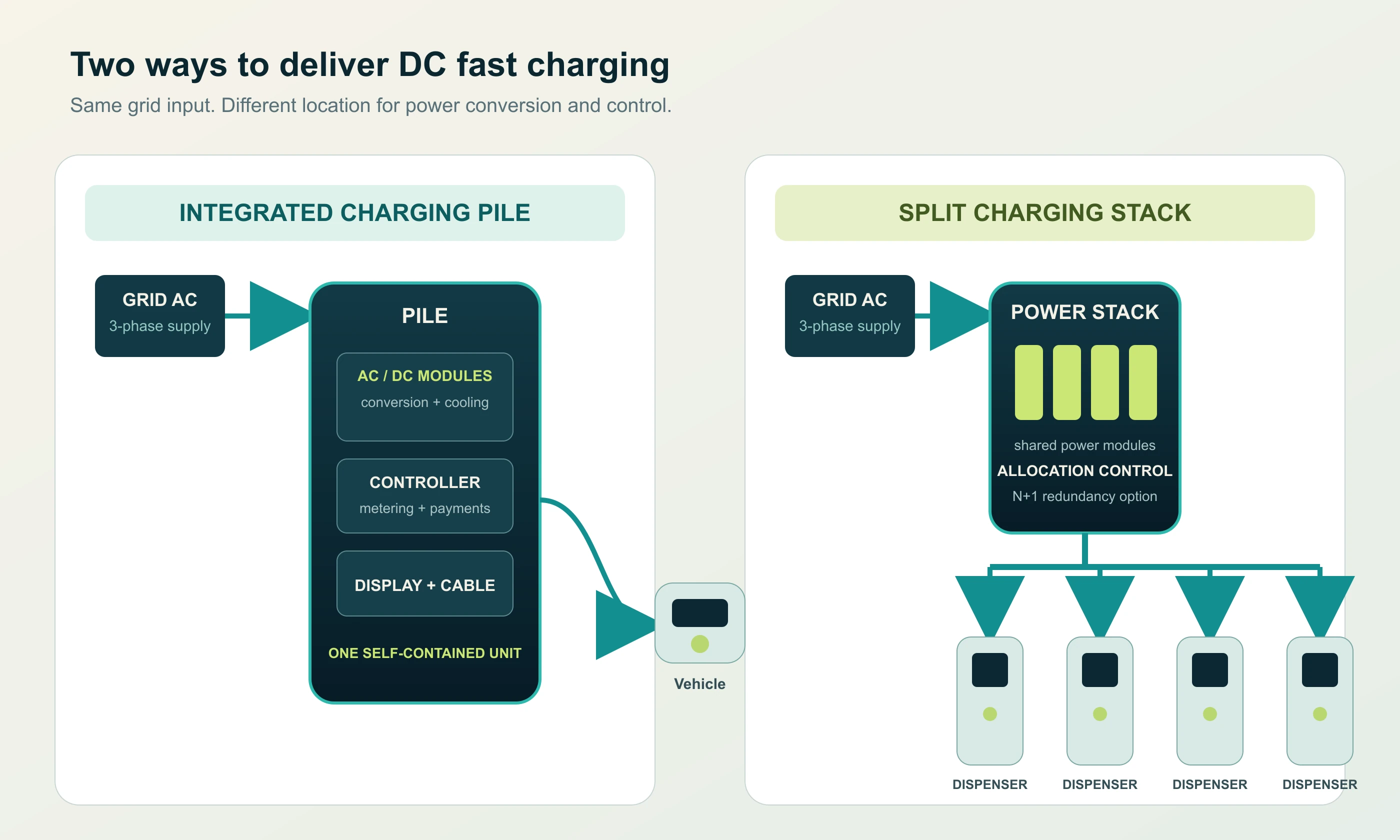
A charging pile is normally a self-contained unit. Its power modules, controller, metering, screen, cable and connector sit inside one enclosure, and the unit allocates power to its own one or two charging guns. A charging stack separates those functions: a central power cabinet contains the high-power conversion modules, while one or more smaller dispensers provide the user interface and charging cables. The stack can move power between bays as driver demand changes.
That distinction changes far more than the equipment layout. It affects how much power each vehicle can receive, how the site expands, how a fault is contained, where heat and noise are concentrated, how much DC cabling is required and how much the project costs over its operating life.
This guide explains the architecture in practical terms for station developers, fleet operators, EPC teams and equipment buyers. It also clarifies the overlapping English terminology, because “charging pile” is common in translated Chinese material but is not the term most American or European drivers use.
Key Takeaways
- A conventional charging pile is an integrated charger; a charging stack is a split power architecture with a central power cabinet and separate dispensers.
- A stack shares one power pool across multiple bays. Total site power—not the sum of every dispenser nameplate—sets the real limit.
- Standalone piles provide simpler deployment and clearer fault isolation. Stacks offer better power utilization and phased expansion at busy, high-concurrency sites.
- A charging stack can serve 400 V and 800 V vehicles, but it is not a battery storage system and does not guarantee maximum power at every dispenser.
- Choose by simultaneous vehicle demand and utilization, not by the total number of parking spaces or the largest kW label in a product brochure.
EV Charging Terminology: Pile, Charger, Station and Stack
The terminology around EV charging is not fully standardized across markets. The same hardware may be described in different ways by manufacturers, utilities, contractors and drivers.
| Term | What it usually means | Important nuance |
|---|---|---|
| EV charging pile | One charger or charging terminal | Common in Chinese and Asian export materials; less common in everyday North American English |
| EV charger | A device that supplies energy to an EV | Broad consumer term covering AC and DC equipment |
| EVSE | Electric vehicle supply equipment | Technical term for the equipment between the electrical supply and the vehicle |
| Charging station | A charger or a complete charging location | Context decides whether it means one pedestal or the whole site |
| Charging dispenser | A user-facing terminal in a split DC system | Contains the interface, cable and connector, but may not contain the main power modules |
| Charging stack | A centralized power architecture feeding multiple dispensers | Not a universal standards term; verify the vendor’s exact topology |
Equipment buyers may still encounter EV charging pile in product documentation and sourcing conversations. In the body copy, however, “charger,” “charging terminal,” “dispenser” and “EVSE” are often clearer for an international audience.
The word “stack” also needs qualification. In the technology industry, a software stack means a layered application environment. Even in EV charging, some companies use “charging stack” to describe an operational or software platform. For procurement documents, define the physical scope explicitly: centralized DC power cabinet, DC distribution, controllers and separate charging dispensers.
What Is an EV Charging Pile?
An EV charging pile is a charger installed as a discrete unit, usually on a floor foundation or wall bracket. The common commercial DC version integrates:
- AC input protection and metering
- AC-to-DC rectifier or power modules
- DC output switching and protection
- a local controller and communications gateway
- a display, card reader or payment interface
- one or two charging cables and connectors
- cooling, filters and environmental protection
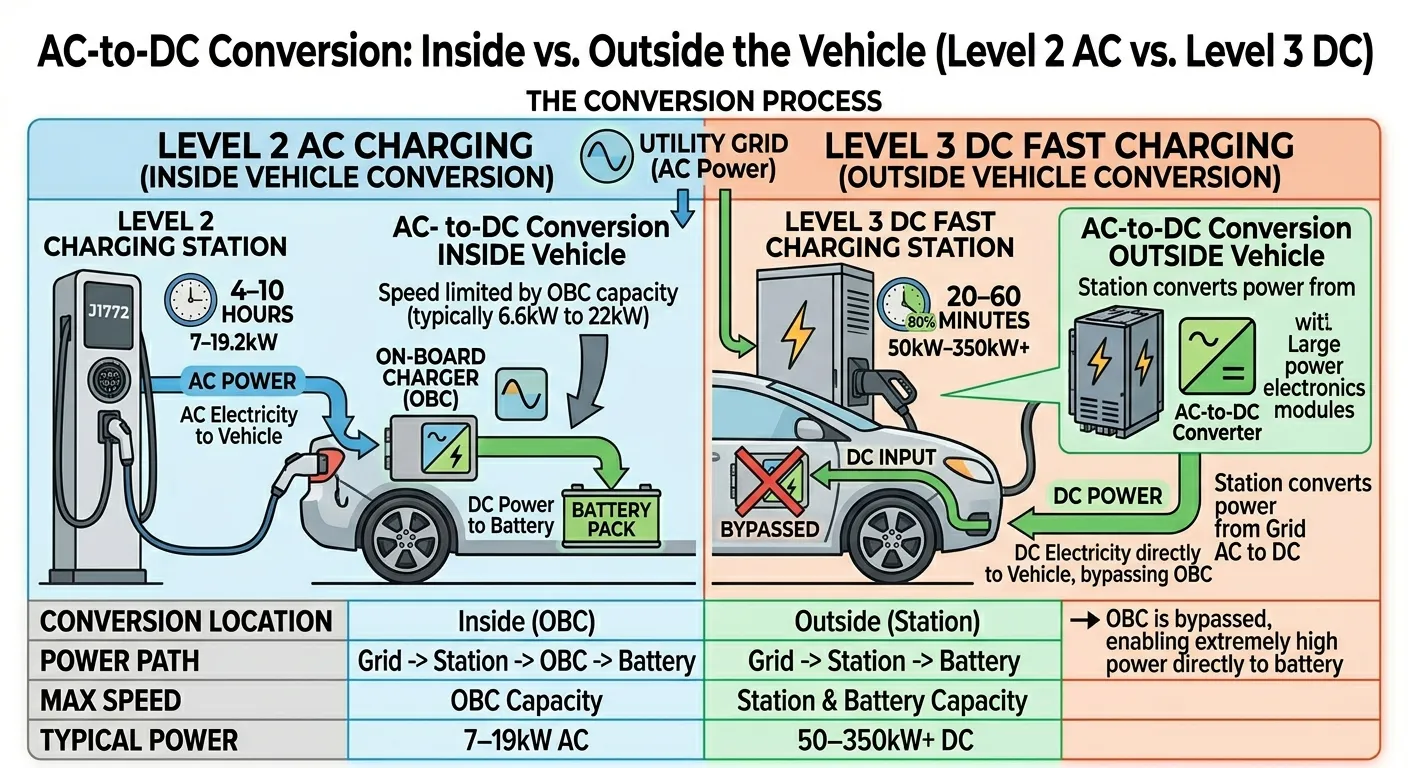
When a driver plugs in, the charger converts grid AC power to the DC voltage and current the vehicle can accept. Because the conversion hardware is inside that charger, its output is tied to the capacity of its own power-module set.
How a standalone charging pile allocates power
A dual-gun charging pile may share its internal modules between two connectors. If the unit is rated at 180 kW, the total delivered to its two vehicles cannot normally exceed 180 kW. One vehicle may receive most of the output while the second is idle, and the controller proportionally reduces both when simultaneous demand exceeds the unit limit.
This local power sharing is useful, but it stops at the enclosure. Two separate 180 kW piles do not automatically become a 360 kW pool. Each operates with its own power modules, controller and fault boundary unless a higher-level site controller coordinates their setpoints.
What “charging pile vs charging station” means in practice
People often use the two terms interchangeably, but they are not always identical:
- A charging pile generally refers to one physical charger or terminal.
- A charging station may refer to that same charger, but it can also mean the whole commercial site.
- A complete station can include transformers, switchgear, chargers, payment systems, lighting, signage, parking access and a charging management system.
For that reason, a page targeting “charging pile vs charging station” should begin by clarifying the scope. A pile is a component; a station is often the operating environment around one or more piles.
What Is an EV Charging Stack?
An EV charging stack is a split DC fast-charging architecture. Instead of putting a complete power-conversion system beside every parking bay, it concentrates the rectifier modules and primary power control in one or more central cabinets. Separate dispensers are installed at the bays and connected by DC feeders.
A typical system has four functional layers:
- AC grid interface: transformer, switchgear, metering and protection.
- Power stack or power cabinet: AC-to-DC modules, DC bus, cooling and module-level control.
- Dispensers: screen, authentication, cable, connector and vehicle communication.
- Site control layer: power allocation, charge scheduling, OCPP communications and energy management.
The separation lets the system treat several dispensers as one aggregate charging resource. If only one vehicle is charging, it can use surplus capacity within the limits of its dispenser, cable, connector and vehicle. When more vehicles arrive, the controller divides the available power according to configured rules.
Centralized and distributed are relative terms
Suppliers sometimes call a stack “centralized” and sometimes call it “distributed.” Both descriptions can be correct at different layers:
- Power conversion is centralized in a shared cabinet.
- Charging interfaces are distributed across the parking bays.
- Control may be centralized in a site controller or distributed among intelligent units.
The important question is not which label the brochure uses. It is where the power modules sit, how DC power reaches each dispenser and what the guaranteed power-allocation logic is under simultaneous load.
What a charging stack is not
A charging stack is not inherently a battery, an energy-storage system or a megawatt charging standard. It can be combined with on-site batteries, solar generation or a microgrid controller, but those are additional systems.
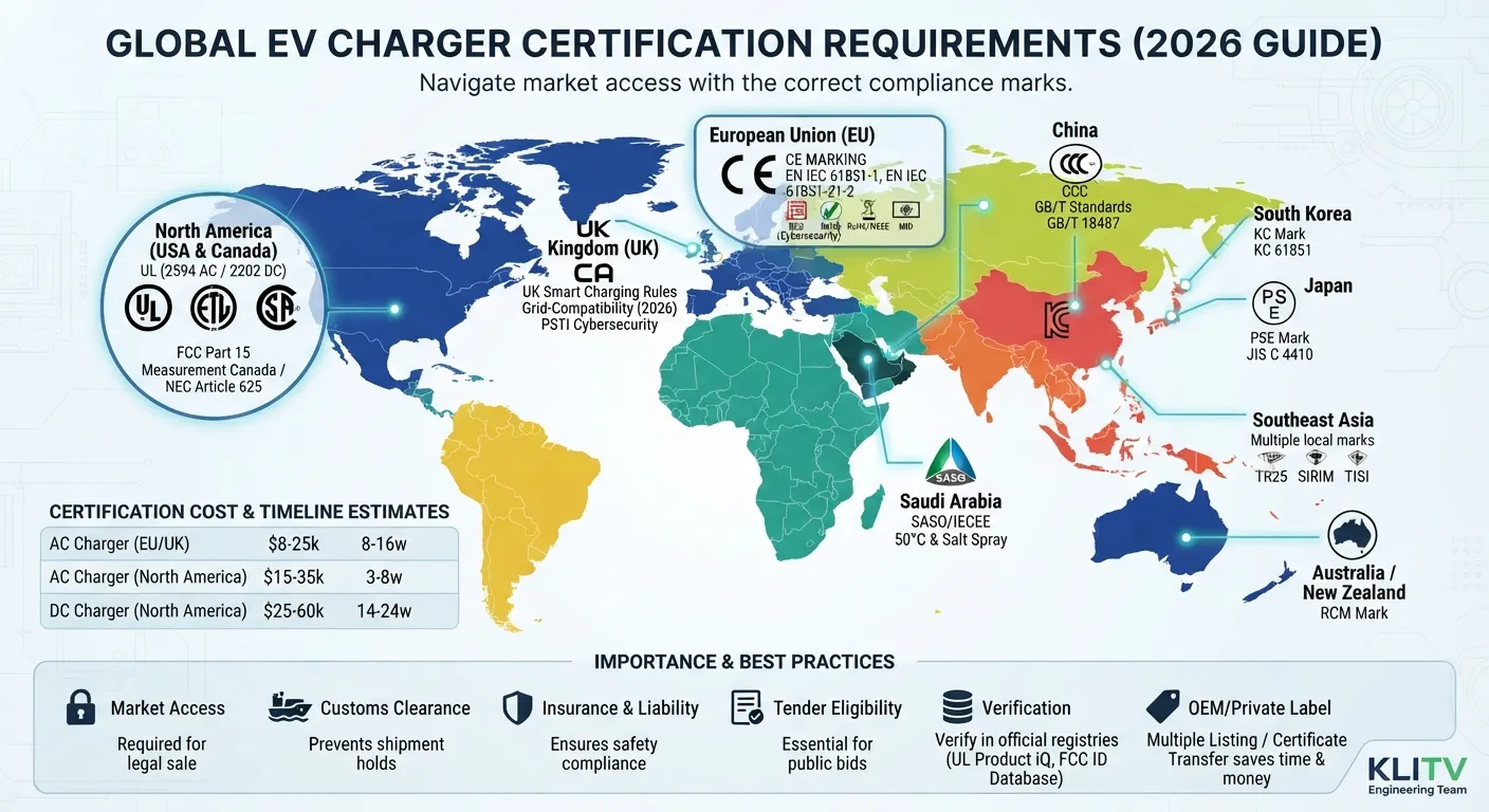
Nor is “stack” a certified category under IEC, UL or GB/T. The project still needs to demonstrate compliance at the assembly and site level, including charger safety, connector compatibility, protection coordination and grid connection requirements.
Charging Pile vs Charging Stack: Side-by-Side Comparison
| Decision area | Standalone charging pile | Charging stack |
|---|---|---|
| Power electronics | Inside each charger | Concentrated in one or more central cabinets |
| User interface | Integrated with the power unit | Separate dispenser at the parking bay |
| Power sharing | Between guns on the same unit | Across all dispensers controlled by the stack |
| Site-level power limit | Sum of independent charger behavior unless externally managed | Shared power pool with a configurable aggregate limit |
| Expansion | Add another independent charger | Add dispensers or power modules, subject to cabinet and bus capacity |
| Fault boundary | Failure usually affects one charging unit | A central failure can affect multiple bays unless redundancy is designed in |
| Maintenance access | Each unit is maintained at the parking area | Power work can be separated from the user area |
| Footprint | Larger equipment beside each bay | Smaller dispensers at bays; central cabinet elsewhere |
| Site cabling | AC distribution to each charger | AC to the central cabinet, then DC distribution to dispensers |
| Installation complexity | Lower for a single unit | Higher at system, protection and commissioning level |
| Best fit | Small or phased sites with low simultaneous demand | Busy depots and hubs where utilization varies across bays |
The comparison is a set of trade-offs, not a hierarchy. A stack is not automatically the premium choice, and a pile is not obsolete. The correct architecture depends on how many vehicles charge at once and how efficiently the site needs to use a constrained grid connection.
The Critical Difference: Power Allocation
The easiest way to understand the difference is to look at simultaneous demand.
Suppose a site has 480 kW of installed charging capacity and four vehicles arrive together.
With four separate 120 kW charging piles, each vehicle can receive up to 120 kW independently. If one vehicle leaves, the other three continue at their own 120 kW maximum. The unused 120 kW remains tied to the empty charger.
With a 480 kW charging stack and four dispensers, all four vehicles draw from the same 480 kW pool. At maximum simultaneous demand, the average allocation may be 120 kW per bay. If two vehicles finish charging, the remaining vehicles may receive more—provided the dispensers, cables, connectors and vehicles can accept the additional power.
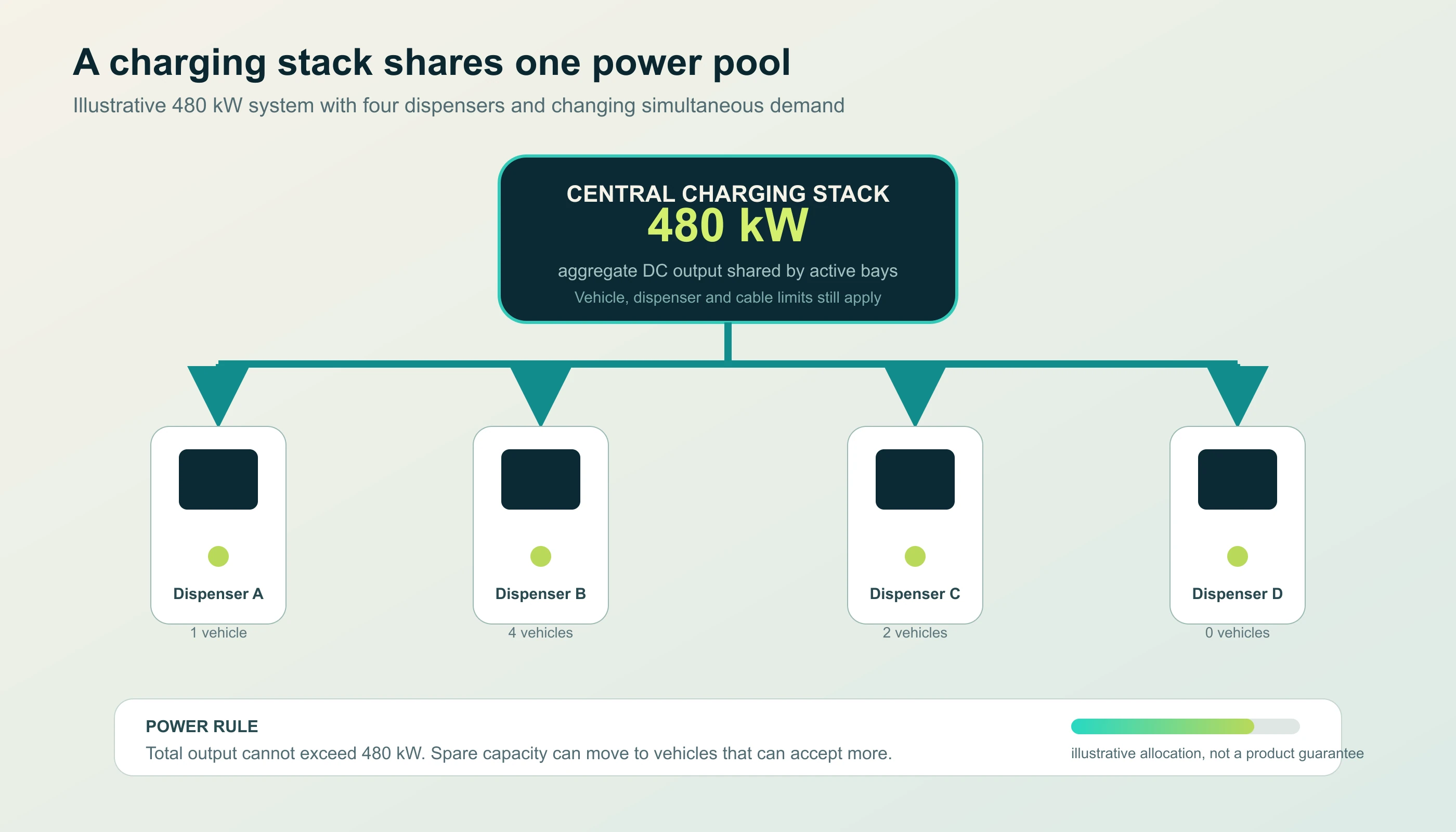
The practical benefit grows when vehicle dwell times are uneven. A short-stop highway customer may need maximum power for 10 minutes, while a fleet vehicle may accept a lower rate for an hour. A stack can follow that changing demand instead of reserving power for an idle bay.
Nameplate power is not guaranteed per bay
A vendor may describe a system as “480 kW” without stating whether that figure is:
- total installed power-module capacity
- maximum AC input power
- maximum aggregate DC output
- maximum power available to one dispenser
- sum of dispenser nameplates
Those values can be very different. A four-dispenser system may use 120 kW dispenser nameplates but deliver 240 kW to one vehicle under an over-allocation strategy. Another system may cap every dispenser at 120 kW even when the central cabinet has spare capacity.
Procurement documents should require a power-allocation table showing expected output for one, two, three and four simultaneous vehicles, including the conditions required to reach each number.
Charging speed remains vehicle-limited
A high-power stack cannot force energy into a vehicle faster than the vehicle accepts it. Charging power falls as the battery state of charge rises, and it can be limited by:
- battery voltage and current limits
- state of charge
- battery temperature and preconditioning
- onboard vehicle software
- connector and cable thermal limits
- dispenser output limits
- site allocation rules
This is why a 400 kW dispenser does not add “400 kW” to every connected car. The system supplies the lower of site capacity, equipment capability and vehicle demand.
Performance and User Experience
At a lightly occupied site, a well-designed stack can deliver a strong driver experience because available power is not stranded behind idle dispenser hardware. The user-facing equipment can also be lighter and quieter because the largest heat sources and power modules sit in the central cabinet.
At a fully occupied site, the driver experience depends on allocation policy. If every bay has equal priority, all vehicles may slow down. If the site uses first-come priority, earlier sessions may retain more power. Fleet depots may instead prioritize vehicles with a departure deadline or a low state of charge.
Standalone piles offer a simpler expectation: each charger has a stated independent maximum. This can be easier to explain to public customers and easier to model when each bay is leased to a different operator.
The best user experience therefore comes from aligning the commercial model with the technical allocation model:
- Public highway hub: prioritize quick turnover and high-power sessions.
- Fleet depot: prioritize departure schedules and overnight readiness.
- Retail parking: cap demand charges and serve many medium-duration sessions.
- Mixed-use site: reserve guaranteed capacity for premium bays if promised to tenants.
Reliability, Redundancy and Maintenance
A stack can be more reliable or less reliable than a row of independent piles depending on its redundancy design.
Standalone piles: simple fault boundaries
If one charging pile fails, the other piles continue operating. The failed unit can often be isolated and replaced without shutting down the site. This modularity is valuable at small sites where a single bay outage is tolerable and specialist service resources are limited.
The trade-off is duplicated equipment. Every pile has its own controllers, power modules, cooling and enclosure, even if it rarely operates near full power.
Charging stacks: shared capacity with system-level risk
A stack can use N+1 power-module redundancy so that one failed module reduces maximum output rather than stopping all charging. It can also move power away from a faulty dispenser and keep the remaining bays operational.
However, a failure in a shared controller, DC bus, protection system or main cooling circuit can affect multiple dispensers. The architecture must include:
- clearly isolated DC output branches
- module-level fault detection and automatic derating
- safe isolation points for maintenance
- spare-module strategy and remote diagnostics
- cooling monitoring and filter service access
- a documented behavior when one dispenser or power section fails
A central power cabinet also concentrates heat and noise. That can be an advantage if the cabinet is located away from drivers, but it becomes a liability if the equipment room is poorly ventilated or difficult to service.
Cost: Which Architecture Delivers Better Value?
There is no universal answer. Compare total lifecycle cost rather than equipment price per kilowatt.
Where a charging stack may save money
- Fewer power modules are installed for the same total site capacity.
- Power is redirected to active bays instead of sitting idle.
- Smaller dispensers reduce equipment footprint at premium parking positions.
- Power modules and service access can be centralized.
- Expansion may avoid replacing complete chargers at every bay.
Where a charging stack may cost more
- DC feeders, protection and site coordination add engineering scope.
- The control and allocation system is more complex.
- Commissioning and staff training take longer.
- A central outage can have a larger revenue impact.
- Long DC cable runs can add losses, voltage drop and installation cost.
Where adding independent piles may cost less
- Low-utilization sites rarely need site-wide power pooling.
- A small first phase can be commissioned one charger at a time.
- Each charger has a simpler procurement and replacement boundary.
- Sites without skilled operators benefit from equipment that behaves independently.
Model the decision across the project life: equipment, civil works, switchgear, transformers, cabling, software, maintenance, downtime, expansion and the revenue lost when drivers cannot access full power.
Installation and Site Design Considerations
The charging stack adds design variables that a single pile does not.
Grid capacity and demand management
The incoming supply must support the site’s realistic peak, not an impossible scenario in which every dispenser operates at its theoretical maximum. Use a load profile based on vehicle arrivals, dwell times and energy demand. If the grid connection is constrained, the stack controller can cap aggregate power, but the operator must understand the resulting service level.
DC distribution distance
Keeping the power cabinet near the dispensers reduces cable length and voltage drop, but the cabinet may then occupy valuable parking or public space. A separate equipment compound improves service access but increases DC feeder length. Electrical engineers should evaluate fault current, protection coordination, cable sizing and thermal performance.
Environmental protection and cooling
Outdoor dispensers need appropriate ingress protection and condensation management. The central cabinet needs filtered airflow or liquid cooling with a maintenance plan. In hot climates, module derating can reduce the promised output if the cooling system and cabinet placement are inadequate.
Communications and cybersecurity
The dispensers, power cabinet and site controller must exchange status, limits and fault data reliably. The communications design should include:
- deterministic local control if the cloud connection drops
- OCPP-compatible charger management where required
- role-based access and protected service interfaces
- logging for power-allocation decisions and fault events
- software-update and recovery procedures
Standards and acceptance testing
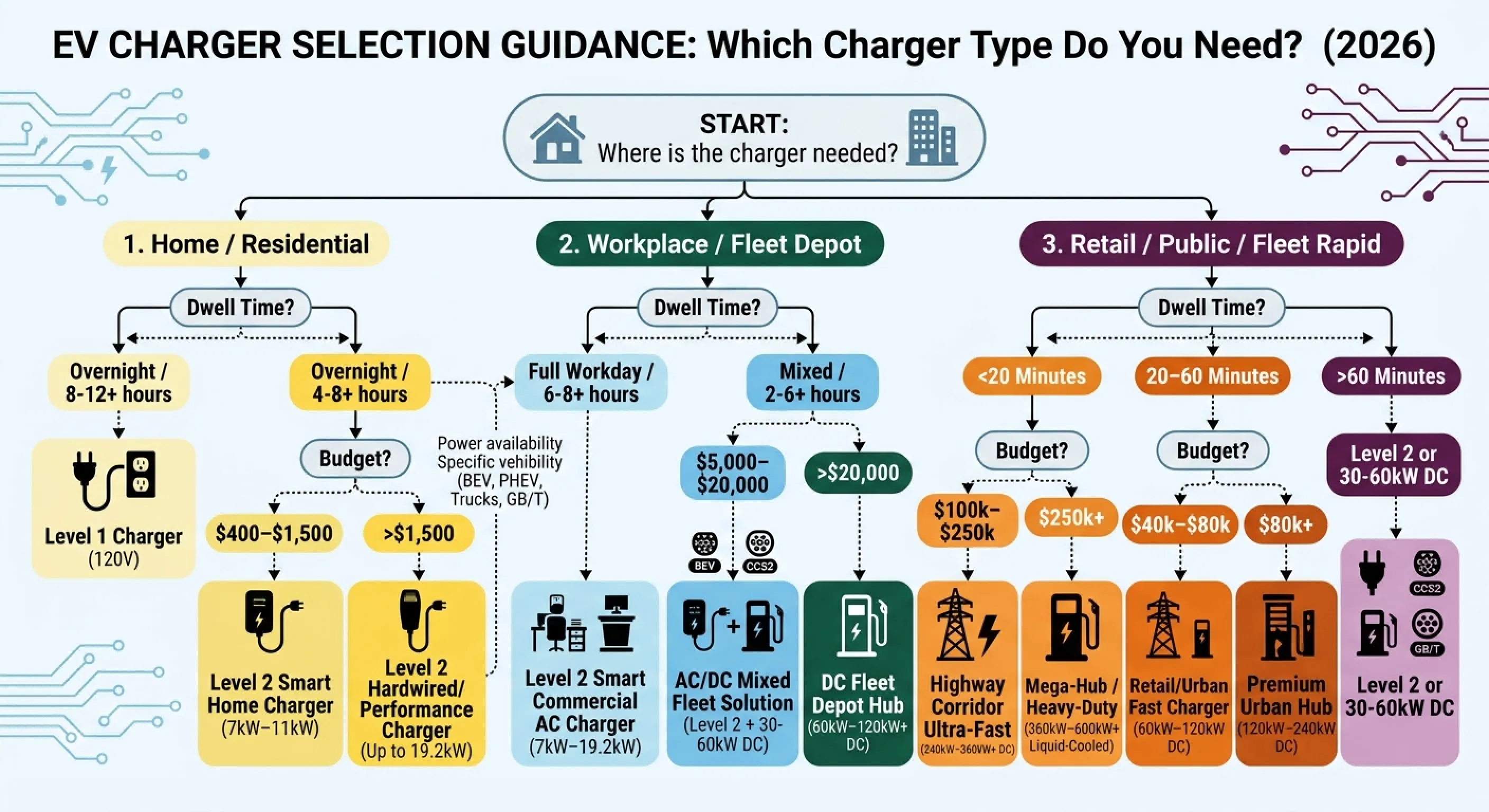
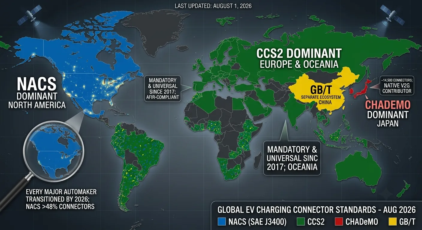
Both architectures must meet the electrical and charging standards applicable to the destination market. This may include IEC 61851 and IEC 62196, UL or other recognized certification schemes, connector standards such as CCS, NACS or GB/T, and cybersecurity or grid-code requirements.
Acceptance testing should include more than a single successful charging session. Test simultaneous charging, power-sharing transitions, dispenser isolation, module failure behavior, emergency stop, communications loss and the maximum site-demand limit.
When to Choose a Charging Pile
A standalone charging pile is often the better choice when:
- the site has one to four charging bays
- simultaneous high-power charging is uncommon
- each bay needs a simple, independent commercial relationship
- installation must be phased one charger at a time
- service teams prefer clear per-unit fault isolation
- the charger can be placed close to the electrical supply
- the site primarily needs AC overnight charging rather than shared DC power
Examples include small retail car parks, workshops, hotels, clinics, offices and early-stage fleet depots with low or predictable concurrency.
Product selection still matters. A multi-gun all-in-one charger with internal module sharing can deliver some of the benefits of a stack within a compact site. Compare its actual simultaneous-output curve with the vendor’s headline maximum.
When to Choose a Charging Stack
A centralized charging stack is usually worth evaluating when:
- six or more high-power bays will operate at the same location
- vehicle arrival and dwell times are difficult to predict
- the grid connection is smaller than the sum of every dispenser’s maximum
- the operator needs site-wide power limits or demand-charge control
- there is a strong case for phased expansion
- premium bays need small dispenser footprints
- module redundancy and hot-swappable service are valuable
- a central operations team can monitor the system remotely
Highway hubs, bus depots, logistics fleets, taxi and ride-hailing hubs, ports and large mixed-use developments commonly fit this pattern.
For a fleet project, pair the architecture decision with a proper duty-cycle analysis. Our fleet charging depot design guide explains how vehicle routes, dwell time and site capacity determine the charger mix. A 480 kW stack is not useful if the site can never supply 480 kW or if the vehicles only accept 60 kW overnight.
Charging Pile vs Charging Stack: A Practical Decision Framework
Use this sequence to avoid designing around a brochure specification:
- Count simultaneous vehicles at the peak hour. The total number of parking bays is less important than how many need energy at once.
- Calculate energy demand, not just power demand. Multiply the vehicles’ energy needs by expected arrivals and dwell time.
- Set the minimum acceptable power per bay. Define fast-charge, standard and overnight service levels.
- Confirm the real grid limit. Include transformer, demand charges and future load.
- Compare the simultaneous-output tables. Do not compare only total kW or the maximum of one dispenser.
- Define redundancy and outage tolerance. How much revenue can be lost if a central cabinet or one dispenser fails?
- Model future expansion. Can modules, cabinets or dispensers be added without rebuilding the site?
- Verify lifecycle support. Ask for module lead times, service response, training and local certification.
If the site’s peak concurrency is low and predictable, independent piles usually win on simplicity. If utilization is high or variable, and the grid connection is a material constraint, a stack often creates more value by pooling capacity.
Common Misconceptions
“A stack is simply a more powerful charging pile”
No. A stack is an architecture with a shared power pool and separate dispensers. Its advantage is coordination, redundancy and allocation—not merely a larger kW number.
“Four guns on a 480 kW stack means four independent 480 kW chargers”
No. The dispensers share the stack’s total power. Individual output depends on dispenser ratings, cable and connector limits, vehicle demand and allocation policy.
“An all-in-one charger cannot share power”
Many dual-gun charging piles share power between their own connectors. The limitation is that the sharing area ends at the enclosure unless an external site controller coordinates multiple units.
“Centralized power is always cheaper”
It can reduce duplicated equipment at high-utilization sites, but it adds DC distribution, control and commissioning scope. Low-demand sites may never earn back that added complexity.
“A charging stack includes battery storage”
Usually not. Storage is an optional separate system. A stack can be grid-only, or it can be integrated into a site with batteries and solar if the design supports it.
“More kW always means a faster customer session”
The vehicle’s charging curve, battery temperature and state of charge often determine the session. Site power should be matched to actual vehicle acceptance and driver dwell time.
Procurement Checklist
Before approving either architecture, ask the supplier for:
- a single-line electrical diagram
- AC input and DC output ratings under stated temperature conditions
- simultaneous-output tables for one, two, four or more dispensers
- a written power-allocation policy
- module redundancy and fault-derating behavior
- connector, cable and voltage-range specifications
- certification file and applicable standards
- communications, OCPP and cybersecurity details
- environmental rating and cooling requirements
- foundation, clearance and DC-cable installation drawings
- spare-parts list, module replacement procedure and service training
- expansion limits for future dispensers and modules
- factory acceptance and site commissioning test plans
For a wider technical overview of charger tiers and AC/DC operation, see our guide to the types of EV chargers. For definitions used in this article, see the EVSE, OCPP and charging management system glossary entries.
Choosing the Right Charging Architecture
The shortest answer to charging pile vs charging stack is this: a pile concentrates power and user equipment at the bay, while a stack concentrates power equipment centrally and distributes the user interface across the site.
A charging pile gives you simple, independent capacity. A charging stack gives you a shared power pool, system-level allocation and more expansion options. Neither is universally superior. The right choice depends on peak concurrency, grid capacity, uptime requirements, service strategy and how much the site will grow.
If your project has one or two bays, start with an appropriately sized standalone charger. If you are planning a hub, depot or multi-bay public site, compare the simultaneous-output data and design the power architecture before ordering dispensers. That single step prevents the most expensive mistake in commercial EV charging: buying the largest number on the specification sheet without confirming what every bay can deliver when the site is busy.
Klitv supplies DC fast-charging equipment for public hubs, commercial properties and fleet depots, including modular high-power systems and 360–600 kW liquid-cooled DC chargers. Share your site plan, vehicle mix and peak concurrency with our engineering team, and we can help map the right charging architecture for your project. Request a technical consultation.